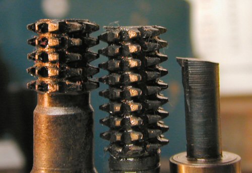
I have to jump forward in time to show the keyway cutter, on the right in this photo. It's square "rifle sight" is 3mm wide. I mount the drilled & reamed gear in the horizontally mounted rotary table's chuck, lower the cutter down into the gear's 12mm hole, and move the table in until the cutter touches the edge of the hole, zero the dial on the Y-axis, then repeatedly raise and lower the mill head as I slowly advance the table in a few thou at a time, cutting the keyway into the gear to slightly over 1/2 of 3mm, or ~.060" for a finished keyway slot.
Also, I bought an Enco 12mm reamer to do perfect mounting holes in the gears. Right on the tight borderline between sliding fit and press fit, just like when the lathe's gears were still brand new...!
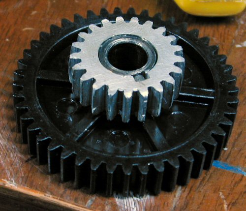
Since you cannot easily see the 21 tooth gear
mounted in position B when set up to do the spiral hob thread, here it is ready
to mount on the lathe. The gears are:
A-60, B-21, C-45, D-65
That gear combo gives a 8.089 TPI "thread" with a theoretical pitch of .123624675, awful darn close to the perfect theoretical circular pitch of .12368475, or 8.085 TPI "thread" for a Mod 1 spiral spur gear cutter. I have since found this is plenty close enough for meshing and working with the stock Mod 1 lathe gears just fine...!
The .004 difference in TPI is of course per 1 inch in length - since only 3 or 4 teeth fully engage between any two gears, the difference is so miniscule it can safely be ignored for my needs.
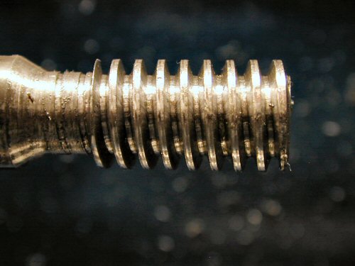
Here I've cut the 8.089 TPI thread, using the same home ground, flat tipped thread cutter tool that I used to make the straight cutter hob. (You already saw the completed spiral hob at the top of this page, center of pic).
Then it was over to the mini-mill to slit-saw the threads into cutting teeth just the same as I'd done with the straight hob, and again using the roughing end mill to do the relief angles behind the teeth. Refer to the straight hob on the previous page if you need to review how I did that. Same technique is again used for my "Woodruff keyseat cutter".
I'm assuming the gear gets a "keyway" while the shaft gets a "keyseat", just going by sale ad terminology.... :-)
I found that my rotary table is too stiff and hard
to turn with it's worm gear disengaged, so I had to make some kind of free
spinning gear blank holder, and while I was at it, I might as well make it with
a 12mm diameter keyed shaft identical to the lathe's (and other future
project's) gear shafts keyed for 3mm.
WOODRUFF KEYSEAT CUTTER-->
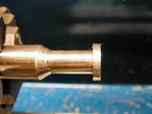
I cut a simple ring into the end of some 5/8" drill rod. 3mm is .118"
wide, but I left the ring .120" wide since I knew I would want to remount
it in the lathe and clean up the rough edges left by slit-sawing the ring into
cutting teeth. I later took it to .118" when cleaning it up. And that is how
you make a "Woodruff keyseat cutter". TRY finding one for 3mm!
Just make you own, save money and get exactly what you need....!
Since I had a big hunk of nylon plastic handy, I cut out a rough cube on my bandsaw, and used my 1/2" roughing end mill on the mini-mill to square up all the sides with each other, ending up with a cube 2" on a side.
I also have a bunch of 608Z rollerskate ball bearings (8mm ID, 22mm OD), so I drilled a hole though for an 8mm shaft with plenty of clearance, and used the biggest endmill I have, 3/4", to start a hole on each end to press fit in the ball bearings on each end...
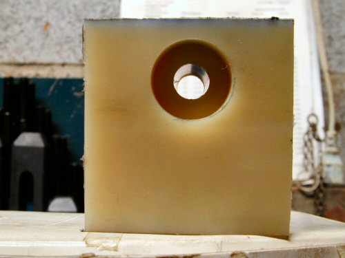
Here I've already bored out one end to press fit in a 608Z ball bearing (that fit so well it was too much trouble to take it out, so I just left it in there), and flipped the cube around.
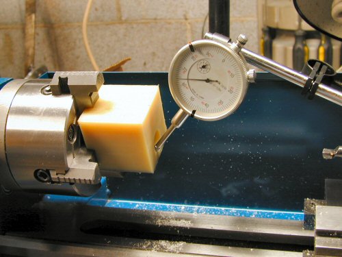
I center it up nicely as shown with a dial indicator, and proceed to bore it out to 22mm, pausing and test fitting the ball bearing repeatedly until I can finally firmly press it in there using my thumb. Done!
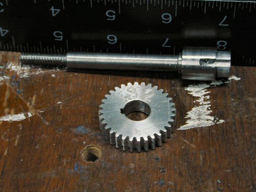
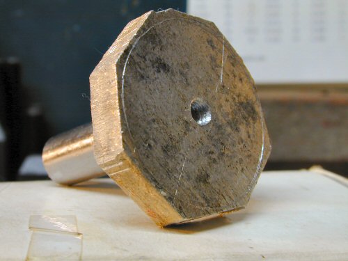
I then took a roughly 4" length of 5/8" CRS bar and turned most of it to 8mm as you can see in this pic with a ruler for scale, with one end turned to 12mm and a short length left just under the original 5/8" diameter (turned down just enough to spin true).
Turned one end to .25" and threaded 1/4-20, and drilled and tapped the other end internally 1/4-20 for the socket head cap screw and washer that will hold the gear on, just like on the lathe.
(That 32 tooth gear stamped "32" is a jump forward in time to the first gear cut using the spiral hob!).
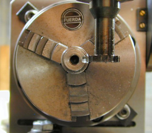
Jumping out of sequence a bit again, here is a shot of my homemade 3mm "Woodruff keyseat cutter" doing the keyseat in the above shaft, for my "free spinning gear blank holder".
I wanted a 32 tooth gear so i can cut 25 TPI threads, according to an abundance of good mini-lathe gearing info found here.
Since a 32 tooth gear requires a 1.339" diameter disk, I scribe a circle slightly larger than that on some scrap 5/16" aluminum plate and roughly cut out around it on my bandsaw. Drill & tap #12-24 in the center and thread it onto my 1/2" gear making bar which is turned down & threaded to fit same on it's end. I then patiently turn it down to round in the lathe, but this time I drilled and reamed it to 12mm, cut a 3mm keyway and fit it on my new holder shaft shown above while still oversize. I replaced it in the lathe and turn down to 1.339" to ensure perfect concentricity, and THEN mount it in the rotary table to cut the 32 "starter gashes" .025" deep. The spiral hob's teeth will engage with them and spin the disk while it cuts.
Then the shaft with it's perfectly concentric turned to size and pre-gashed gear blank is inserted into the holder block bearings and snugged into place with a nut on it's threaded end. The block is then placed in a vice on the mill and angled up to match the angle of the thread that I cut into teeth on the spiral hob.
A picture is worth a thousand words here, no? :-)
I've tried to explain this concept in messages on the metal working lists but can never find the wording to precisely explain what you can see right here...
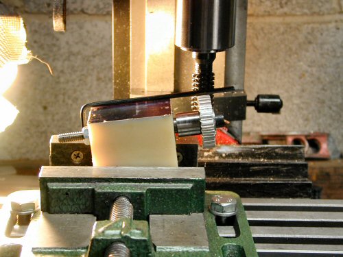
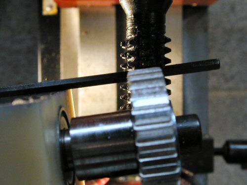
I laid an allen wrench on top of the holder block to act as an aiming device of sorts, to help align the pre-gashed slots in the gear blank exactly with the angle of the cutting tooth thread in the spiral gear cutter. There has got to be a better way to set the angle than just visually like I am doing here, but I just haven't thought of how I could do that at this point.
THIS is the part that is soooo dificult to explain without pictures!
I carefully line up the gear slots with the hob teeth as I feed the work into the cutter, and slowly spin up the mill, and it proceeds to spin the blank as it cuts!
The Potential Price Of Impatience:
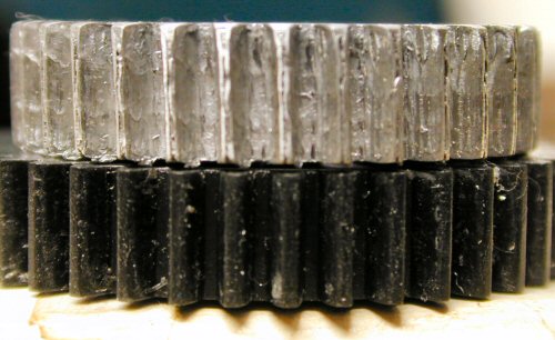
I got bored and started to hurry moving the gear side to side along the x-axis to cut the full width of the gear. I over brightened this pic a bit so if you look real close you can see the teeth were starting to slightly angle to the left towards the top as viewed in this picture.
I was able to salvage this first attempt into a usable gear by later remounting it as shown above and cutting just a few thou deeper, and much more slowly from side to side. Trying to hurry causes the gear to get pushed into spinning faster so the cutting teeth adjacent to the center of the hob's center height cut upward more, and so that side (in this case the left as shown above) starts looking lower as it spins around to the front where you can see it... DON'T HURRY and make sure you have that gear blank exactly correctly angled..!
Some Important Notes:
When the pre-gashed gear blank is mounted and angled properly, arbitrarily pick one tooth near the center of the cutter hob, and align that tooth exactly to the center height of the gear blank. That is the one tooth that will make all the deepest cuts all around, and is why the cutting will make a "wowwowowowow" sound even though you can see everything is visually spinning nice and true.
You need to move along the x-axis to cut the full width of the gear. Avoid climb milling. You can HEAR the difference in sound when you advance the center height cutting teeth off the edge of the disk, so doing full passes is easier because you can HEAR when you have gone off the edge far enough for a full pass, but still before the gear stops spinning since it is angled and other teeth above or below center are still engaging it enough to keep it turning. Practice will quickly make this much clearer to you.
In the set up exactly as shown above, I finally settled into a pattern of moving the table left until the hob center was just off the right side of the gear blank. Advance in .005" and WAIT for the gear blank to complete a full revolution. Move the table a few thou to the right (causing the gear blank to move rightward into the hob) and WAIT for the gear blank to complete at least one full revolution. I keep repeating this move & wait pattern until I could hear I was finally moving off the left side of the gear blank. Slowly crank my way back to the starting point, advance another .005" and then repeating the above until full depth is finally, eventually reached.
Always remember that the one cutter tooth that you set to exact center height is doing ALL of the deepest cuts and always give it lots of time to work its way completely around the gear blank before moving on. This is why you must move in tiny steps along the x-axis, waiting for a full revolution of the gear blank between each step, especially as you are nearing completion of the gear. Happily, as you cut deeper you can speed up the mill to cut down the waiting time for the gear blank to complete a full revolution quite a bit, so all those tiny x-axis steps followed by waiting for a complete turn of the gear blank aren't quite as time consuming as it may sound.
While this makes for slow & patient going to make a spur gear, the alternative of using a straight hob for a 100 tooth gear would require setting the rotary table/dividing head and making a cut 800 times! Compared to THAT this is a much more workable poor man's set up, especially since this one hob will do from 12 teeth to a rack (well, almost a rack, but plenty close enough for anything I'll ever need in Module 1 size).
Either that or drop a few hundred bucks to buy a complete set of 8 gear cutters, or grind a fly cutter bit specific to the gear you want to make, assuming you have a gear to use as a guide, or etc.
This is not a perfect solution, but since I already had some 5/16" thick aluminum plate (close equivalent to 8mm), all it cost me for all of the above was about $15 for a 3 foot length of 5/8" O1 oil hardening drill rod at the local Fastenal store. And I avoided the "stupid mistake waiting to happen" from the sheer tedium of repeatedly setting the rotary table/dividing head and making a cut hundreds of times to make a larger spur gear. And that is pretty much that.
If you are wealthy or doing paid work where time is money, by all means just buy the complete set of 8 involute gear cutters for a few hundred buck$ (plus a special arbor for mounting them), to do all the Module 1 gears from 12 teeth to a rack and party on! If you're just a hobbiest on a budget like me, the above can be a workable "time instead of money" alternative for making just what you need without spending much money at all.
Page 1 Page 2